
I saw this design in a book. I’ve always liked the look of certain items of Shaker woodwork. I made a Shaker clock nearly 30 years ago, a piece I’m very proud of. I had in mind to paint this cabinet and decided to use more of the Poplar that I had picked up free, left over from a kitchen refit. I did the right thing this time and stored the wood in the place where the cabinet would be used, in the house, for 5 days prior to construction. First I rough-sawed enough pieces for the project, knowing that most parts would be composed of glued-up boards. In fact only the stiles were from one piece of wood; the back was from four pieces and all other parts were from two. Referring to the cutting list I marked each piece as I cut it. Many of the dimensions in this post are in good ol’ inches because the book was American.

I took that lot to the house and left it there to acclimatise. I stacked it so that plenty of air could circulate around each part. I monitored the moisture levels and saw it drop from 13% down to about 10% over five or six days, after which I took it back to the workshop to start the project. I first planed one side of each piece flat on the planer (‘jointer’ to USA folk).

Then I used the bandsaw to resaw to slightly more than the intended thickness

After doing the first piece I decided to change the blade in my bandsaw for something more suitable to the task of resawing all this wood, namely a ¾” 3 tpi blade.

It was a new blade I had got with the machine, and it was terrible. I’ve never experienced so much noise, vibration and general racket from any blade in the past. I used it to cut the rest of the stock, expecting the blade to fly apart at any minute. It held together OK. Some of the pieces of Poplar showed quite attractive streaks of darker, purple-coloured figuring once resawn

Once I had resawn all the parts, I put them through the thicknesser (‘planer’ to USA people), reducing the thickness to just over ½” (except the pieces for the back, which were 3/8″), allowing for further reduction in thickness once the boards were glued up and planed flat. It was at this point that I had made my first mistake – the pieces that were to form the top and bottom of the cabinet should have been ¾”, but I wasn’t to realise my error until later.

With all the wood now thicknessed, I squared-up one edge of each piece on my shooting board and glued the various pairs together to make the wider boards needed for the project. I made sure all the grain directions were lined up so that I could plane the faces later without tearout caused by planing against the grain. If you don’t take this measure you’ll end up with a board where one half of it has a different grain direction to the other half so the only way to plane it would be to plane each half in opposite directions, but in practice that just wouldn’t allow you to plane the whole board flat, as one piece.


Inevitably, after gluing pieces together to make a wider board there is always a very slight ridge along the glue line where the pieces didn’t line up exactly. Following on from my experience during the last project, I planed the composite pieces flat using my smoothing plane. This is a very rewarding experience compared with using a machine. For a start the boards were now too wide to be smoothed using my thicknesser so I couldn’t use that. The belt sander is too inaccurate for this task and would create lots of dust.

Planing by hand has the following advantages:
- Quieter – no noise of machines and dust extractor – just a gentle ‘swoosh’
- You get shavings instead of dust, so less particulate matter in the air
- Good exercise – it’s quite an aerobic activity
- Smoother surface – you end up with a glass smooth surface not available from most machines (with the exception of the very expensive industrial fixed-blade ‘super surfacers’ from Japan).
- Better for the environment (no electricity used)
- More rewarding experience – better for the soul!


The only disadvantages I can think of are that it’s slower and you need to sharpen the blades and set the plane up, but that also applies to some extent with machinery. And you have to clear all the shavings away!

With all parts now glued and surfaced, I then cut them to final width and length using the table saw. I left the door part slightly too wide, to be fine-tuned later. First I cut the dados into the side pieces using the radial arm saw, using a stop block on the fence and then micro-adjusting the width of the dados until the shelf pieces fit snugly


I used the RAS and the router table to run a matching rabbet around the outside of the top and bottom pieces. Once I’d cut the dados I did a dry-fit of the sides, shelves, top and bottom. It was then that I noticed that the back was too narrow – the four pieces I’d used hadn’t quite managed to achieve the required 11″ width. It was about 3 mm too narrow. I pondered whether to ‘fix’ this by reducing the width of the whole cabinet to match, meaning I’d have to reduce the width of the shelves and also the width of the top and bottom and also adjust the rabbet in the top and bottom. It sounded like a lot of work. As the cabinet was ultimately to be painted, I decided to make the back wider by adding a couple of bits of wood (off-cuts from earlier), and then I could trim back to the proper 11″ width.


It didn’t look pretty at this point, but once it was planed smooth, trimmed and painted, nobody would be any the wiser! I ripped the back part to 11″ cutting off some of the extra bit I’d added

With the back piece now of sufficient width it was time to cut the curved profile around the top. Using a scaled up print-out of the profile that was included in the book, I made a template by first gluing the print-out to a scrap piece of 9 mm ply

… then cutting with the bandsaw

… and smoothing with the spindle sander

… and drilling a ½” hole to help align the template on the work.

I then used the template to trace the profile onto the work piece, flipping the template to form the mirror image

I cut close to the line using the bandsaw

and smoothed it out on the spindle sander.

I then cut the hole in the back piece

… and elongated the ‘keyhole’ shape using a 6 mm spiral up/down cutter in my router table, using a piece of wood clamped to the table to act as a guide


I next made a knob for the door. I didn’t have any Poplar big enough so I used African Mahogany. It didn’t match, but it was to be painted anyway, so no worries. I made it the same way as I had made the knob for my candle sconce, by cutting the blank using a hole saw, inserting a dowel and then ‘turning’ it by rotating it in a drill against the blade of the bandsaw:
It’s crude but it works. With the knob still in the drill I spun it against abrasive paper to smooth the shape. Then I cut off the unwanted part using the bandsaw

I next made the turn button that will hold the door closed. After cutting the rough shape out on the bandsaw I smoothed it to shape on the belt sander.

I used a block plane to form a thumbnail profile around the edges of the top and bottom parts.

With all the parts now made, it was time to assemble the cabinet. I first glued the sides, shelves, top and bottom together.

I also used some panel pins on the top and bottom, drilling holes first to prevent the wood from splitting.
Next I attached the right-hand stile, using just glue

I didn’t fix the left-hand stile in place yet. It was easier to leave it as a separate piece while I mounted the door hinges to it and generally adjusted the door to fit. I found some old brass hinges I’d saved from an old sideboard years ago, probably c.1930’s. I clamped both pieces together in a vice and marked the position of the hinges using a marking knife

I sawed across both pieces using a fine-toothed pull saw, keeping to the inside of the line left by the marking knife.

I intended to rout out the wood between the cuts using my hand-held trimmer, but I realised that the base of that tool was too small to span the eventual gap that would be created and would ‘fall’ into the hinge mortice as the supporting wood was removed. So I clamped to scrap pieces of wood either side to support the base of the trimmer. This would also help prevent any tear-out.

I set the depth of cut to be just thicker than the thickness of the hinge leaf, so the hinge would end up lying slightly below the surface of the wood. This was to ensure a small gap between the door and the style once the door was closed (these hinges had quite a large gap between the leaves when closed, hence the deeper mortice). I freehand routed out between the lines keeping just within the lines


I used a 12.5 mm chisel to trim the mortice right up to the original cut line.


… and tried the hinge for size

Perfect fit! Then, using a self-centring hinge bit,,

I drilled the mounting holes for the hinges

..and then attached the hinges to the door and the stile (for authenticity I should have used brass slotted head screws, but as these are not visible from outside I just used a modern type of screw).


Then I did a test-fit of the stile/door assembly

I progressively trimmed both the door and the stile, width-wise, so that the left side of the stile was flush with the side of the cabinet while leaving a nice consistent gap where the door closes. I used my Record No.7 Jointer plane.


This plane had, at the time of this project, been for sale on eBay, but I was so impressed with its ability to take long even shavings from the edge of the pieces that I immediately took the eBay listing down. This plane was a pleasure to use and I decided to keep it.
At one point I had to trim the edge of the stile where it overhung the side of the cabinet. Instead of repeatedly planing the edge and testing for fit, I decided to take the scientific approach. I measured the overhang using my digital vernier caliper. It was 0.9 mm.

Then I measured the thickness of the shavings coming from the plane, 0.05 mm

So, theoretically I needed to take 18 (0.05 x 18 = 0.9) passes with the plane to remove the required amount. So this I did and it was close enough. Using a steel rule and several layers of masking tape to act as a spacer, to ensure an even gap when the door is closed, I glued the left hand stile in place

Once the glue had dried I trimmed the stile flush using a block plane and my Record No.077 Bullnose Plane to reach the ends where the block plane couldn’t go.

I screwed 2 cleats to the back of the door to help keep it straight. I used a scrap block of wood to act as a depth stop on my drill to save drilling right through the front of the door!

I drilled the holes in the cleats slightly oversized to allow for some wood movement.
I trimmed the back to size and fitted it with screws. There would be no point gluing this wide piece to the conflicting grain direction of the rest of the cabinet. It’s bound to move slightly over time. I fitted the door knob and countersunk the hole using my latest countersink bit, which left a nice clean finish

After a final test assembly, I took off the hinges, back, knob and turn-button and sanded the whole lot down using my random orbit sander

Then came the time to distress it. I rolled and dropped a lump of broken concrete on my nice new cabinet, then attacked it with a rasp and dropped various sharp tools onto it from height, to simulate knocks and prangs that an old cabinet might have suffered over the years.

I was worried I had gone too far with the ‘damage’, but once I later stained it, I realised I probably hadn’t gone far enough! It’s very difficult to smash up something you have carefully made!

The original intention was to paint the cabinet, but I decided to stain it initially, partially to see what it looked like and also so that when I ‘wear out’ the paint later, it shows as a darker colour underneath. I had made no effort to fully clean up any glue squeeze-out so there were some patches that didn’t stain correctly.
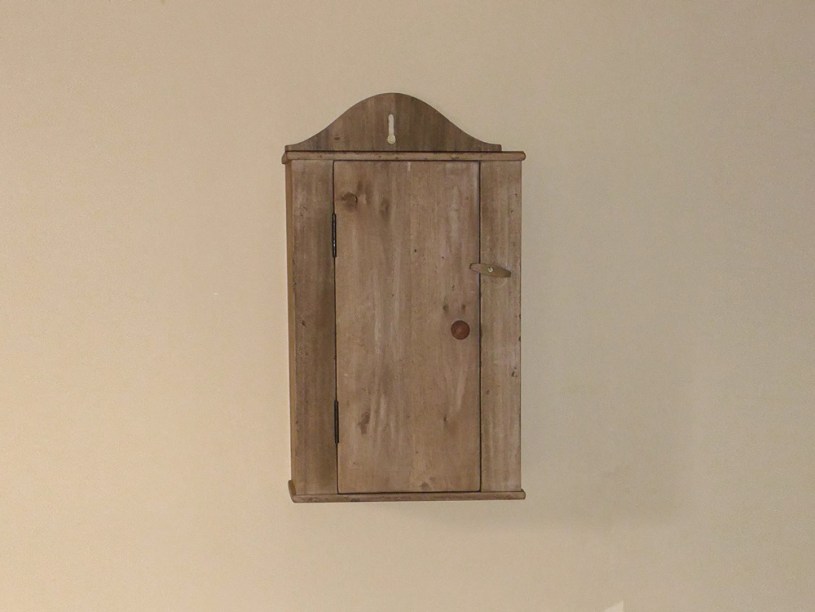
I reassembled the cabinet and hung it on a wall to see what it looked like.

If I ever get round to painting it I’ll show that in another post, but that’s all for now for this cabinet. One thing that I realised while making this is how much more attention to detail, patience and skill is required to make something like this compared to a bread board. I guess that’s why they call the artisans of the craft ‘cabinet makers’ and not ‘bread board makers’! Not that this is anywhere close to ‘fine furniture’ in terms of quality – just sayin’..
Gallery
Click an image to enlarge it and scroll through other images.


Tools used
- Jig saw
- EMF (pinless) moisture meter
- Table saw
- Bandsaw
- 6″ Belt sander
- Spindle sander
- Mirka random orbit sander
- Router table
- 12.5 mm flat bit (router, rabbeting base and top)
- 6 mm spiral up/down cutter (router table, for ‘keyhole’ slot)
- Radial Arm Saw (rabbeting base and top, and shelf dados)
- Router trimmer
- 10 mm straight bit (hinge mortices)
- Pillar drill
- 9 mm bit (for jig)
- 12 mm forstner bit
- Self-centring hinge bit (for hinges)
- Veritas Low-Angle Block Plane
- Record No.4 Smoothing Plane
- Record No.7 Jointer Plane
- Record No. 077 Bullnose Plane
- Marking knife
- Marples 12 mm chisel
- Various sash clamps / F-clamps
- Steel rule
- Digital caliper
- 6″ steel engineers square
- Pencil
- Printer
- Diamond rasp (for distressing)
- Lump of concrete (for distressing)
Materials used
- Poplar
- African Mahogany (for knob)
- 9mm plywood (for template)
- 20 mm panel pins
- Pair of old 2″x ½” brass hinges
- ¾” x no.6 brass slot head screw (for turn button)
- 3.5 x 16 mm pozidrive wood screws for hinges (12x)
- 3.5 x 20 mm pozidrive wood screws for door cleats (4x)
- 3 x 20 mm pozidrive wood screws for knob and back (5x)
- Rustins Medium Oak wood stain
- Gorilla wood glue
- A4 paper
Things that worked well
- Mounting the hinges to both door and stile before fitting the stile was so much easier.
- Record No. 7 Jointer plane was superb. I decided not to sell it!
- Hand-routing out the hinge mortices using 2 support pieces worked well – a jig would have made it even easier!
- Distressing by rolling a rock and dropping things on it did a good job of ageing – need to do more next time!
Things that didn’t work (and improvements)
- Somehow the keyhole feature was not in the exact centre of the back part. The look of this is made worse by the fact that the visible board join is also not in the centre, but the other side of it, making the error visually worse – this last issue would go away if I painted the cabinet (which would hide the join)
- I thicknessed the top and bottom pieces to ½” instead of ¾”. Need to pay more attention!
- I don’t like the way that the back is just stuck on the back of the cabinet – this has the effect that the lips of the top and bottom pieces don’t reach fully to the wall. It also means that you can see the edge of the back when the cabinet is viewed from the side. This join between the back and side is likely to move under different humidity conditions, so won’t always look flush. But that was the original design. If I were to make another one, all these issues would be solved if the sides extended to the wall and the back was recessed inside.
